LOGDRAFT report forms can include a column showing a monitoring well installation schematic similar to the one shown below:
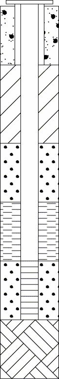
Monitoring Well Schematic
Just like a real monitoring well, LOGDRAFT's well schematics are built piece-by-piece: for each different piece installed in the physical well you need to enter something into the tabulated subsurface section of the data entry form (see this figure). Well schematics are built by selecting pieces from the Monitor Well Details section of the legend file associated with the project (see this page). If you'd like to see what pieces are available, follow the instructions for printing a comprehensive legend that are given in this section.
The basic idea is that you need to tell the program about every change in either the well pipe or the backfill by picking a new well piece from the legend file. As an example, if you used a sand packing at 15 feet, you would have a card on the subsurface section with a depth of 15 and the well piece called SAND in the well schematic data entry field. (The 15 foot card could also be used for entering any sampling data or soil descriptions taken at that depth.) Continuing with the example, if you went to a slotted pipe at 18 feet, your next data entry card would have a depth of 18 and SLOTTED in the well schematic field.
This figure shows a data entry form filled in to produce the earlier example.

Data Entry Form for Well Example
The -.3 indicates a riser extending 0.3 feet above the ground surface; the 19 indicates the boring termination depth (the "END" section of the well extends from 16 to 19 feet).
To enter a monitoring well schematic
- Create or open the boring's folder.
- For each depth where a piece was changed on the monitoring well -- either the pipe or the backfill -- you'll need to have a card on the boring's subsurface data entry section (see this figure) listing the depth of the change and what changed.
If the monitoring well was capped by a riser extending above ground, start a new data entry card: In the Depth field for the card, enter the above-ground height of the riser as a negative number (for example, if the riser extends 0.3m above ground level, enter-0.3as the depth).
If the well started at ground level, start off with the 0-depth card. - Each card on the boring's subsurface data entry section (see this figure) should have a field titled something like Monitoring Well Installation Schematic. A small button will be located just to the right of the field: click it.
Clicking on the button displays the Monitoring Well Installation dialog : - If your data entry form doesn't have anything similar, your report form probably doesn't include a monitoring well column -- consult the Customization Guide for instructions on adding one.
- The Monitoring Well Installation dialog is divided into two tabs: the Top Caps tab and the Subsurface tab. Top Caps is where you'll find monitoring well caps: If the monitoring well was capped, click on the closest match to the actual cap used then click on the OK button.
If the well wasn't capped, click on the Subsurface tab and select the closest match to the top section of the monitoring well, then click on the OK button. - Proceeding to the card with next depth where something was changed, again click the button next to the monitoring well data entry field. Click on the Subsurface tab then choose the next section of the well. Repeat this procedure for the remaining sections.
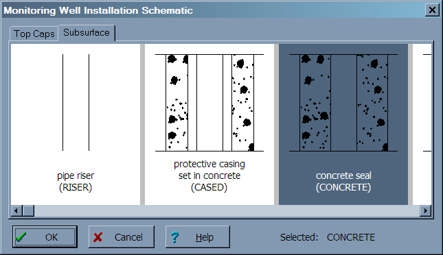
Monitoring Well Installation Dialog
- You can add new types of monitoring well sections by following the instructions given in this section.
- Each well section has an ID which is shown in parenthesis on the Monitoring Well Installation Schematic dialog: Once you have these IDs memorized you can skip clicking on the button to display the dialog -- instead, just enter the ID into the data entry field to the left of the button.
- If you ended your monitoring well before the end of the hole, you can select the
BLANKwell section at the end-of-well depth to show an empty block of well below that depth. Note that this will show an empty rectangle between the end-of-well depth and the bottom of the boring: If you would like to remove the rectangle, edit the WELL legend table and erase theEbackfill pattern from the card that hasBLANKin the Well ID field.